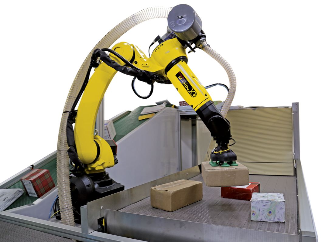
A typical robotic sorting system with a vacuum gripper head uses a large, remote mounted, blower or pump to generate vacuum. The blower is connected to the gripping head using vacuum rated tubing and a valve is added to control vacuum to the gripping head. When we built these sorts of vacuum setups, we would place one large valve on the 3rd axis of the robot. There are two major drawbacks with this configuration. One is the time it takes to apply vacuum to the target and the second is that there is no option for zoning. Zoning refers to when some suction cups on the gripping head are deactivated, usually because full coverage of a small object does not require all of the suction cups.
The time it takes for the vacuum to activate or deactivate on the gripping head is a function of the actuation time of the valve and the time it takes to evacuate air from the hose and gripping head. For many applications, the activation time can be compensated for by offsetting the valve opening time ahead of the expected arrival time of the gripper to the product.

Typical single valve arm
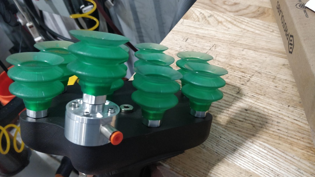
Vacuum valve on gripper

Click here to start customizingWhen the activation time becomes an issues is when the cycle rate of full system approaches the activation time of the vacuum. Modern advances in machine vision have pushed these types of sorting systems into sub 2 second cycle times. That is, that the robot will retrieve a product from a sorting bin, present the product to a barcode scanner, deposit the product onto a conveyor belt and return to the bin for a new product within 2 second. The actuation time of the large valve described is around half of a second and at these short cycle times, many products would be dropped or mishandled.
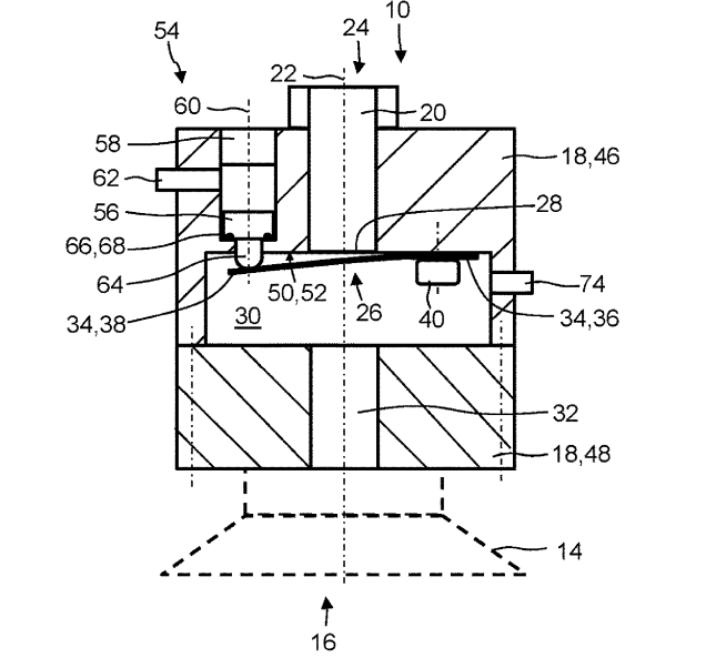
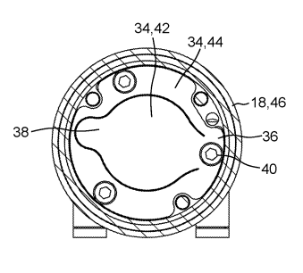
My solution to this problem is now called US20220379495A.
"A valve device comprising a valve housing with a flow channel having a fluid outflow side and a fluid inflow side, a leaf spring having a fastening portion and a free portion. The fastening portion is connected to the valve housing such that, in a closed configuration, the free portion bears against a valve seat and that, in order to bring about an open configuration, the free portion, from the closed configuration, can be elastically bent away from the valve seat, and an actuating device which is designed to transfer the leaf spring from the closed configuration to an open configuration against an elastic reset force of the leaf spring."


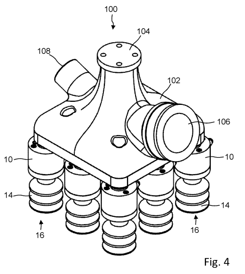

This solution drastically improves activation time of the vacuum and also allows for zoning of the suction cups while still using a single blower for the source of vacuum. The advantage of this solution lies in the fact that the valving has been moved as close to the suction cup as possible. This means that all of the air can be evacuated from the vacuum lines before the valve is opened. The valve itself is opened by a compressed air line moving a piston which is orders of magnitude quicker that the large single valve. Since each suction cup must be commanded on individually, the cups can be activated in whichever configuration is best for the product being handled. Additionally ports were add to this device to supply a burst of compressed air, used to break the suction when dropping the product, and to monitor the pressure inside each suction cup.
This project was the outcome of my own initiative and resulted in the first design patent awarded to the USA branch of Schmalz. This valve concept is being released as its own product line from Schmalz as well as integrated into existing product lines.